In the intricate world of modern industrial automation, where precision, speed, and reliability are paramount, understanding the subtle nuances of system performance can be the difference between peak efficiency and costly setbacks. At the heart of nearly every automated process lies a network of sensors, diligently gathering data from the physical world and translating it into actionable information for control systems. Yet, the journey from physical event to digital response is rarely instantaneous. This delay, often overlooked but profoundly impactful, is critically influenced by two key concepts: sensor response time and automation latency. These two seemingly technical terms are intertwined, shaping everything from the accuracy of a robotic arm to the stability of a chemical process. A slower sensor or an inefficient control loop can introduce significant lag, leading to reduced throughput, compromised product quality, increased energy consumption, and even safety hazards. This comprehensive guide will delve into the definitions, causes, effects, and mitigation strategies associated with sensor response time and its crucial role in defining the overall latency of automated systems, empowering engineers and automation professionals to design more responsive, reliable, and efficient operations.
The Foundation: Deconstructing Sensor Response Time
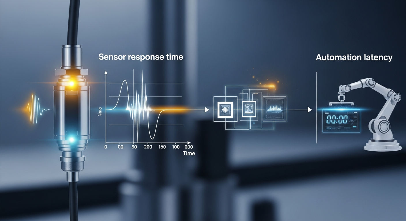
At its core, a sensor’s purpose is to detect and quantify a physical phenomenon. However, no sensor can react instantaneously. The time it takes for a sensor to register a change in its environment and produce a stable, accurate output signal reflecting that change is known as sensor response time. This fundamental characteristic is a critical determinant of how quickly an automation system can perceive and react to dynamic conditions.
Defining and Measuring Sensor Response Time
Sensor response time is not a single, universally defined value, but rather a set of specifications that describe the sensor’s dynamic behavior. Common metrics include:
- Rise Time (T₁₀-₉₀ or T₀-₉₀): This refers to the time it takes for the sensor’s output to rise from 10% to 90% (or 0% to 90%) of its final stable value after a step change in the measured input. It indicates how quickly the sensor can initially respond.
- Settling Time (Tₘ): This is the time required for the sensor’s output to settle within a specified percentage (e.g., ±2% or ±5%) of its final stable value. It reflects the sensor’s ability to reach and maintain an accurate reading.
- Delay Time: The initial time lag before the sensor’s output begins to respond to an input change.
- Time Constant (τ): Particularly relevant for first-order systems (like many thermal sensors), the time constant is the time it takes for the sensor’s output to reach approximately 63.2% of its final value. A smaller time constant indicates a faster response.
Understanding these specifications from a sensor’s datasheet is crucial for predicting its real-world performance.
Factors Influencing Sensor Response Time
Numerous elements contribute to a sensor’s inherent response time:
- Sensor Technology and Physical Principles: Different sensing technologies inherently have different response speeds. For instance, an optical sensor detecting a presence can be nearly instantaneous, limited by light speed and electronics. In contrast, a thermocouple measuring temperature requires time for heat to transfer to its sensing junction, making it significantly slower. Chemical sensors, which rely on reactions, often exhibit even longer response times.
- Measurement Range and Resolution: Sometimes, sensors with wider measurement ranges or higher resolutions might trade off some response speed due to the internal processing required to achieve those specifications.
- Environmental Conditions: The operating environment can profoundly affect response time. For a temperature sensor, factors like ambient temperature, airflow, and the thermal mass of the object being measured directly influence how quickly the sensor can equilibrate and provide a stable reading. Pressure sensors might be affected by the viscosity of the fluid.
- Signal Conditioning and Filtering: Raw sensor signals are often noisy and require filtering to improve accuracy and stability. While essential, these filters (e.g., low-pass filters, moving averages) inherently introduce a delay. Aggressive filtering can significantly increase response time.
- Output Interface and Communication Protocol: The method by which a sensor transmits its data can also introduce delay. Analog outputs are generally faster than digital, but digital offers noise immunity. Digital communication protocols (e.g., I2C, SPI, Modbus, Ethernet/IP) have varying data rates and overheads, impacting how quickly data packets arrive at the controller.
- Physical Construction: The physical design of the sensor, including material properties, size, and packaging, plays a role. A robust, heavily potted sensor might be more durable but could have a longer thermal response time than a delicate, exposed sensor element.
Engineers must carefully consider these factors during sensor selection to ensure the chosen device meets the dynamic requirements of the application.
Unpacking Automation Latency: More Than Just a Delay
While sensor response time is a crucial piece of the puzzle, it’s just one component contributing to the broader concept of automation latency. Automation latency refers to the total time delay between a physical event occurring in the real world and the automation system executing a corrective or responsive action based on that event. It’s an end-to-end measurement of the system’s overall responsiveness.
The Chain of Delays: Components of Automation Latency
Automation latency is a cumulative effect of delays occurring at various stages within a control loop. Understanding each component is essential for optimizing system performance:
- Sensor Response Time: As discussed, this is the initial delay for the sensor to accurately reflect the physical change. This is the first link in the latency chain.
- Signal Propagation Delay: The time it takes for the electrical or optical signal from the sensor to travel through wires or fiber optic cables to the data acquisition system or controller. While often negligible over short distances, it can become a factor in large-scale distributed systems.
- Data Acquisition/Sampling Delay: The time taken for the controller or data acquisition system to read the sensor’s output. This is inversely related to the sampling rate. If a sensor updates every 1ms but the controller only samples every 10ms, an additional 9ms of latency can be introduced.
- Controller Processing Delay (PLC Scan Time): Once the data is acquired, the controller (e.g., PLC, IPC) needs time to execute its logic, algorithms, and calculations. This includes reading inputs, executing control programs, performing arithmetic operations, and updating outputs. In PLCs, this is often characterized by the “scan time,” which is the time it takes to complete one full cycle of input reading, logic execution, and output updating.
- Network Latency: In distributed control systems, sensor data might be transmitted over industrial networks (e.g., Ethernet/IP, Profinet, EtherCAT, Modbus TCP). Network latency includes the time for data packetization, transmission, routing, and reception across the network infrastructure. This can be a significant source of delay, especially in systems spanning large areas or involving many network devices.
- Actuator Command Latency: After the controller processes the data and determines an action, it sends a command to an actuator. There’s a delay for this command signal to reach the actuator.
- Actuator Response Time: Finally, the actuator itself (e.g., motor, valve, solenoid) takes time to physically respond to the command and effect the desired change in the physical world. This can be a mechanical, hydraulic, or pneumatic delay.
Why Low Latency is Crucial for Automation Success
The cumulative effect of these delays directly impacts the performance, safety, and efficiency of automated systems:
- Precision and Accuracy in Control: In applications requiring tight control (e.g., robotic path following, precise temperature regulation), high latency means the control system is always reacting to slightly outdated information. This can lead to deviations from the setpoint, poor tracking performance, and reduced product quality.
- System Stability: High latency can destabilize control loops, especially in fast-changing processes. If the feedback arrives too late, the controller might overcompensate, leading to oscillations, overshoot, undershoot, and potentially chaotic behavior.
- Safety: In critical safety systems (e.g., emergency stops, collision avoidance), rapid detection and response are paramount. High latency can severely compromise safety, increasing the risk of accidents or damage.
- Throughput and Efficiency: In high-speed manufacturing, every millisecond counts. Latency directly limits the maximum speed at which a process can operate effectively. Slower response times translate to lower production rates and reduced overall equipment effectiveness (OEE).
- Real-time Decision Making: Many modern automation systems rely on real-time data for dynamic decision-making. High latency hinders the ability to make timely adjustments, adapt to changes, and optimize processes on the fly.
The Critical Connection: How Sensor Response Time Drives Automation Latency
The relationship between sensor response time and overall automation latency is not merely additive; it’s foundational. A slow sensor creates a bottleneck at the very beginning of the control loop, effectively setting an upper limit on the responsiveness of the entire system, regardless of how fast other components might be.
Direct and Indirect Impacts
The most immediate effect is that any delay inherent in the sensor’s response is directly incorporated into the total automation latency. If a sensor takes 100ms to register a change, the control system cannot possibly begin to process that change in less than 100ms, even if the controller and network are lightning-fast.
Beyond this direct addition, there are several cascading and indirect effects:
- Lag in Closed-Loop Control: In a closed-loop system, the controller uses sensor feedback to adjust outputs. A sluggish sensor means the feedback signal is delayed, causing the controller to act on outdated information. This leads to a persistent lag between the actual process state and the controller’s perception of it. For example, in a temperature control system, if the sensor responds slowly to a heat increase, the controller will only detect the rise after a delay, potentially leading to the temperature overshooting the target before corrective action is taken.
- Reduced System Bandwidth: The effective “bandwidth” or responsiveness of an automation system is limited by its slowest component. If the sensor has a response time of T, the maximum frequency at which the system can accurately respond to changes will be limited by T. This means that even if a process could theoretically operate at a higher frequency, the sensor’s limitation prevents it.
- Overshoot and Undershoot: In processes requiring precise setpoint control (e.g., positioning a robot arm, filling a container), a delayed sensor can cause the control system to “overcorrect” or “undercorrect.” The controller might continue to apply power to a motor, for instance, based on a sensor reading that indicates the arm hasn’t reached its target, when in reality, it has already passed it. By the time the updated sensor data arrives, the system has overshot, requiring subsequent corrective actions that consume more time and energy.
- Inefficient Resource Utilization: Investing in high-performance PLCs, fast industrial networks, and rapid actuators can yield diminishing returns if the sensor data feeding them is inherently slow. The faster components will spend time waiting for fresh data, leading to underutilized processing power and network capacity.
- Increased Wear and Tear: For systems prone to overshooting or oscillations due to latency, actuators may be forced to work harder, making more frequent or aggressive adjustments. This can lead to increased mechanical stress, premature wear on components, and higher maintenance costs.
Real-World Scenarios Illustrating the Impact
- High-Speed Packaging: In a manufacturing line packaging products, proximity sensors detect the presence of items on a conveyor belt to trigger a filling or sealing mechanism. If the sensor response time is too slow relative to the conveyor speed, the product might move past the trigger point before the mechanism activates, leading to missed packages or faulty operations.
- Robotics and Collision Avoidance: Collaborative robots or fast-moving industrial robots often use vision sensors or LiDAR for collision avoidance and precise manipulation. A slow response from these sensors means the robot might not detect an obstacle or a human presence in time to react, leading to collisions or safety incidents. For precise pick-and-place operations, even a few milliseconds of delay can result in misaligned parts.
- Process Control in Chemical Plants: Regulating critical parameters like temperature, pressure, or pH in a chemical reactor requires constant feedback. If a temperature sensor has a long thermal response time, an exothermic reaction could run away, leading to dangerous overheating or product degradation before the control system can effectively intervene.
- Machine Tool Control: In CNC machining, sensors monitor tool position, spindle speed, and force. High latency can lead to inaccuracies in cut depth, chatter marks, or even tool breakage if the control system cannot react quickly enough to dynamic cutting conditions.
These examples underscore that sensor response time is not merely a specification but a critical performance parameter that dictates the overall effectiveness and safety of an automated system.
Strategies for Minimizing Latency and Optimizing Responsiveness
Achieving optimal automation performance requires a holistic approach to minimizing latency, starting with a keen understanding of sensor response time and extending through the entire control loop. Here are practical strategies and best practices:
1. Judicious Sensor Selection and Placement
- Match Sensor Speed to Application Needs: This is paramount. Do not overspecify or underspecify. For high-speed applications, prioritize sensors with inherently fast response characteristics (e.g., photoelectric sensors over ultrasonic, fast-response thermocouples over RTDs for dynamic temperature changes). Always consult the sensor’s datasheet for T90, settling time, and other relevant metrics.
- Consider Physical Principles: Understand how the sensor works. If a physical change (like heat transfer or chemical reaction) is required for detection, there will always be an inherent delay. Choose technologies that minimize these physical delays.
- Strategic Placement: Position sensors as close as possible to the point of interest to minimize any physical propagation delays (e.g., placing a flow sensor directly in the main stream rather than a bypass line). Ensure the sensor is exposed appropriately to the phenomenon it’s measuring (e.g., thermal sensor immersed directly in fluid).
- Environmental Considerations: Account for environmental factors that might impede a sensor’s response. For instance, ensure a temperature sensor is well-insulated from ambient air if measuring process temperature to avoid slow response due to external influences.
2. Optimizing Signal Conditioning and Data Acquisition
- Minimal Filtering: While filtering is essential for noise reduction, excessive or inappropriate filtering can significantly increase latency. Use the lowest order and gentlest filter necessary for your application. Understand the phase delay introduced by filters. For critical applications, consider adaptive filters that can balance noise reduction and latency.
- High-Speed Data Acquisition: Employ data acquisition systems or controller I/O modules capable of high sampling rates. The sampling frequency should be at least twice (Nyquist theorem) the highest frequency component of the signal you want to measure accurately. For control applications, much higher sampling rates are often beneficial to reduce acquisition delay.
- Edge Computing: For complex analysis, consider using smart sensors or edge devices that can perform preliminary data processing and filtering closer to the source, reducing the amount of raw data transmitted and potentially lowering overall latency for critical insights.
3. Controller and Logic Optimization
- Efficient PLC/Controller Programming: Write lean, optimized code. Avoid unnecessary subroutines, complex calculations within critical loops, and excessive use of non-deterministic functions. Prioritize time-sensitive tasks.
- Minimize PLC Scan Time: In PLC-based systems, reducing the scan time is crucial. This can involve optimizing code, using faster processors, and distributing processing across multiple controllers if feasible. Some PLCs offer “fast I/O” or “interrupt-driven I/O” capabilities that allow critical inputs to be read and reacted to outside of the main scan cycle, significantly reducing latency for specific events.
- Dedicated Motion Controllers/Industrial PCs: For highly dynamic applications like robotics or high-precision motion control, consider dedicated motion controllers or industrial PCs (IPCs) that offer superior processing power, real-time operating systems, and dedicated hardware for faster execution of control algorithms compared to general-purpose PLCs.
4. Network Architecture and Protocol Selection
- Choose Low-Latency Industrial Ethernet: For distributed systems, select industrial Ethernet protocols designed for real-time performance, such as EtherCAT, PROFINET IRT, Sercos III, or TSN (Time-Sensitive Networking). These protocols offer deterministic communication with very low jitter and minimal latency compared to standard Ethernet or older fieldbuses.
- Minimize Network Hops: Reduce the number of switches, routers, and gateways between the sensor/I/O device and the controller. Each network device introduces a small processing and forwarding delay.
- Dedicated Networks: For extremely critical, high-speed control loops, consider segmenting your network or using dedicated network segments to ensure that control data is not competing with less time-sensitive information (e.g., SCADA, HMI data).
5. Advanced Control Techniques
- Predictive Control Algorithms: Implement advanced control strategies like the Smith Predictor or model predictive control (MPC) which can explicitly account for known system delays (including sensor response time) and predict future process behavior to apply corrective actions proactively, rather than reactively. Kalman filters can also estimate current states based on noisy and delayed measurements.
- Feedforward Control: Where measurable disturbances are known to affect the process, feedforward control can anticipate and counteract their impact before they propagate through the system, often in conjunction with feedback control.
6. Comprehensive System Integration and Testing
- End-to-End Latency Measurement: Do not rely solely on individual component specifications. Thoroughly test the actual end-to-end latency of the entire control loop in a real-world or simulated environment. Use high-speed oscilloscopes, logic analyzers, and specialized diagnostic tools to measure the delay from a physical event to an actuator’s response.
- Iterative Tuning: Control loops often require iterative tuning. Understand how changes in sensor response time affect PID gains or other control parameters. A faster sensor might allow for more aggressive tuning, while a slower one necessitates more conservative settings to maintain stability.
Ultimately, optimizing responsiveness is about making informed trade-offs. Faster components often come with higher costs. Sometimes, a slight increase in latency might be acceptable if it allows for greater stability, reliability, or cost-effectiveness. The key is to understand the dynamic requirements of the application and design the system accordingly, leveraging these strategies to achieve the optimal balance.
Conclusion
In the intricate tapestry of industrial automation, the concepts of sensor response time and automation latency stand as critical pillars, profoundly influencing the precision, stability, and overall efficiency of any automated process. We’ve explored how a sensor’s inherent delay in perceiving and reporting changes is not an isolated phenomenon, but rather the foundational brick in the wall of total system latency. From the physical principles governing a sensor’s operation to the complex interplay of data acquisition, controller processing, and network communication, every stage contributes to the cumulative delay between a real-world event and a system’s corrective action.
A deep understanding of these delays is not merely academic; it is an imperative for engineers and automation specialists aiming to push the boundaries of performance. High latency can lead to a cascade of undesirable outcomes: compromised product quality, reduced throughput, increased energy consumption, system instability, and most critically, safety hazards. By recognizing the direct and cascading impacts of a slow sensor or an inefficient control loop, we can appreciate the immense value in addressing latency holistically.
The journey towards optimized responsiveness involves a strategic combination of careful sensor selection, meticulous signal conditioning, efficient controller programming, robust network design, and the judicious application of advanced control algorithms. It demands a commitment to comprehensive system testing to accurately quantify and mitigate delays. As automation continues to evolve towards smarter, faster, and more complex systems, the demands for near real-time perception and reaction will only intensify. By mastering the principles of sensor response time and automation latency, we equip ourselves to design and implement systems that are not only powerful but also truly responsive, adaptive, and prepared for the challenges of tomorrow’s industrial landscape.